GRP Pipes
- GRP Pipes
- Design
- Benefits
- Production Process
- Product Quality
- Certification & Standards
- Stacking & Storage
- Installation & Other Services
GRP Fitting & Joints
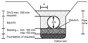
Trench width
The minimum trench width shall provide sufficient working room at the sides of the pipe to permit accurate placement and adequate compaction of the pipe zone backfill material. Suggested minimum trench dimensions are given in Figure.
| Sl.No. | Pipe Diameter (mm) | Dimension ‘A’ (mm) |
|---|---|---|
| 1 | 300 - 500 | 200 |
| 2 | 600 - 900 | 300 |
| 3 | 1000 - 1600 | 450 |
| 4 | 1700 - above | 600 |
Dewatering
Where conditions are such that running or standing water occurs in the trench bottom or the soil in the trench bottom displays a “quick” tendency, the water should be removed by pumps and suitable means such as well points or under drain bedding. This system should be maintained in operation until the backfill has been placed to a sufficient height to prevent pipe flotation. Care should be taken that any under-drain is of proper gradation and thickness to prevent migration of material between the under drain, pipe embedment and native soils in the trench, below and at the sides of the pipe.
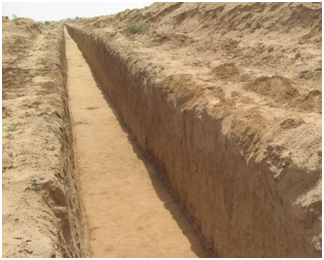
Preparation of trench bottom
The trench bottom should be constructed to provide a firm, stable and uniform support for the full length of the pipe. Bell holes (Figure) should be provided at each joint to permit proper joint assembly and alignment. Any part of the trench bottom excavated below grade should be backfilled to grade and should be compacted as required to provide firm pipe support. When an unstable sub grade condition is encountered which will provide inadequate pipe support, additional trench depth should be excavated and refilled with suitable foundation material. In severe conditions special foundations may be required such as wood pile or sheeting capped by a concrete mat, wood sheeting with keyed-in plank foundation, or foundation material processed with cement or chemical stabilizers. A cushion of acceptable bedding material should always be provided between any special foundation and the pipe. Large rocks and debris should be removed to provide four inches of soil cushion below the pipe and accessories.
Pipe Zone (Embedment) Backfill Materials
Most coarse grained soils as classified by ASTM D2487, Classification of Soils for Engineering Purposes, are acceptable bedding and pipe zone (embedment) backfill materials as given in the adjacent table. Maximum grain size should typically not exceed 1 to 11/2 times the pipe wall thickness or 11/2 inches whichever is smaller. Well graded materials that will minimize voids in the embedment materials should be used in cases where migration of fines in the trench wall material into the embedment can be anticipated. Alternatively, separate the open graded material from the non-cohesive soil with a filter fabric to prevent migration of the smaller grained soil into the open graded material. Such migration is undesirable since it would reduce the soil density near the pipe zone and thereby lessen the pipe support. Embedment materials should contain no debris, foreign or frozen materials.
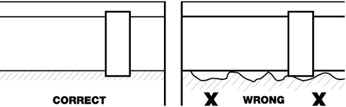
Bedding
A firm, uniform bed should be prepared to fully support the pipe along its entire length (Figure). Bedding material should be as specified on Figure and in paragraph-d. Bedding minimum depth should be equal to 25% of the nominal diameter or 6 inches, whichever is less. A firm trench bottom must be provided (see paragraphs b and c). Initially place and compact bedding to achieve 2/3 of the total bed thickness (normally four inches). Loosely place the remaining bedding material to achieve a uniform soft cushion in which to seat the pipe invert (bottom). After joining pipes, assure that all bell holes are filled with the appropriate embedment materials and compacted as specified. Note - Do not use blocking to adjust pipe grade.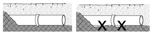
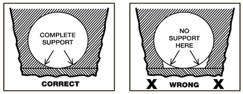
Haunching
A very important factor affecting pipe performance and deflection is the haunching material and its density. Material should be placed and consolidated under the pipe (Figure) while avoiding both vertical and lateral displacement of the pipe from proper grade and alignment.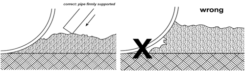
Backfilling
Pipe zone (embedment) material shall be as specified on Figure and in paragraph d. (It must be the same as the bedding material to prevent potential migration.) Place and compact the embedment material in lifts to achieve the depths and densities specified on Figure. Little or no tamping of the initial backfill directly over the top of the pipe should be done to avoid disturbing the embedded pipe. Remaining backfill may be the native trench material provided clumps and boulders larger than 3 to 4 inches in size are not used until 12 inches of pipe cover has been achieved.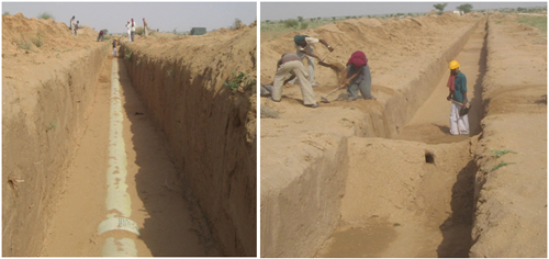
Minimum cover for traffic load application
Sufficient cover depth of compacted fill above the pipe crown prior to application of vehicle loads should be given. Installation in poor soils or at shallower cover depths is possible by using a surface bridging slab or pipe encasement in concrete or similar.
Trench construction in Rock
Minimum dimensions for pipe installations in a rock trench should be as in Figure, where the rock ends and the pipe pass into a soil trench area (or reverse), flexible joints should be used as shown in Figure. Alternatively, use of cement stabilized backfill for the foundation and bedding of a pipe just passing through a rock-soil transition would negate the need to locate a flexible joint at this transition. Trench construction should be according to the method applicable for the native soil condition.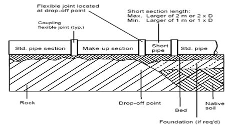
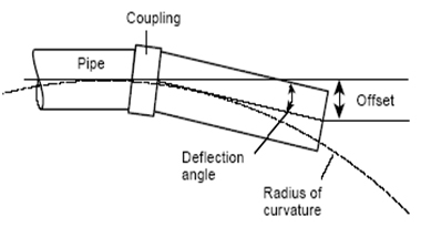
Angular deflections
Maximum angular deflection in service at each coupling taking into account combined vertical and horizontal, must not exceed than the values shown in table. This can be utilized to accommodate gradual changes in line direction. The pipes should be then joined in straight alignment and thereafter deflected angularly as required.| Sl.No. | Nominal Pipe Diameter (mm) | Angular Deflection (Degrees) |
|---|---|---|
| 1 | 350 - 500 | 3.0 |
| 2 | 600 - 900 | 2.0 |
| 3 | 1000 - 1300 | 1.0 |
| 4 | 1400 - 1800 | 0.5 |
| 5 | 1800 - above | 0.25 |
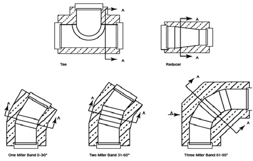
Thrust Blocks
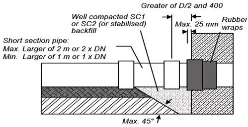
RCC thrust block will be constructed at the places of bends, tees, and reducer or at he places of blinds. It is always recommended to use coupling at both the edges of thrust blocks where pipe comes out of the thrust block. We advise to wrap a band of rubber around the coupling prior to placement of any concrete. Rubber should protrude (25mm) from the thrust block edge, Rubber thickness 10 mm & of 50 Durometer (shore A hardness). It is always recommended to cast thrust blocks as laying progresses. Before the hydro test all thrust blocks should be completed. We always recommend to fix a short pipe piece of 1 to 2 mtr length on each side of thrust block (immediately after block) with coupling joint. This acts as a rocker pipe to provide additional flexibility to the system in case of uneven settlement if any. See figure.Thrust Blocks
Connection- Rubber wrap enclosed in concrete
Buoyancy
Minimum cover required on pipe crown to avoid upliftment of empty pipes in high water table areas is one meter or one diameter whichever is more. If sufficient cover is not available and the area has the possibility of high water table RCC precast blocks or institution blocks of required weight are to be used to counteract unbalanced uplift forces.
Crossing over River, canal or Road
We need to encase the pipe min 300 mm all around with concrete & balance portion of the trench should be backfilled with crushed rock/gravel up to the top of trench. The minimum back fill cover on the pipe should be 1.5 mtr.
Pipe Jointing
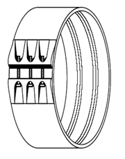
Coupling Joint
Flanged Joints
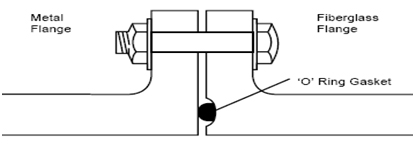
-
Lay-up Joint
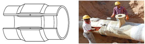
-
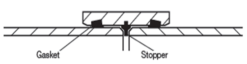
Flexible Steel Couplings
-
Dual bolt mechanical coupling